Actuators
We considered a fair number of devices to actuate our contraption. Our first attempt was with stepper motors.
Stepper motors are very clever devices that can advance one step at a time in a controlled fashion, giving high positional control. They're not very complicated mechanisms and can be had rather cheaply.
The problem is that the controllers behind them are much harder to build and there is no intrinsic mechanism for verifying that the motor has indeed turned the appropriate number of steps. While these can be added afterwards, that's complex and was outside of the scope of the project. Furthermore, a high acceleration torque was essential to our task, and it was very difficult to find a stepper motor that was fast, strong, and cheap. As the joke goes, “Choose any two of the above.”
In the end, our stepper motor tests were disappointing at best. I had a bit of friction in my prototype, I admit, but it was nothing that I would have deemed excessive. I could easily turn the gears with my fingertips. However, the stepper motor just couldn't keep up. It would skip about half of the steps, which for us is catastrophic. This could have been due to any number of reasons, from insufficient voltage, to a poor controller, to an insufficiently powerful motor. However, we're not electrical engineers, and solving these problems was just too much trouble when we had another solution right at hand... servos.
We like servos because everything is contained in one small package. No need to add a gear reduction system, no need to add a sensor to ensure the servo moves correctly, and no need for complicated controllers.
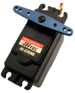
We bought three Hitec HS-5745MG Digital servos and one SSC-32 servo controller card. The servos wound up costing us $60 or so and the controller card $30. Total price was just over $200. Not so bad, eh? (Make certain you buy your digital servos from lynxmotion or another company that will “unblock” them, giving you the full range of movement.)
The only “upgrade” that I performed on the servos was to add a spring underneath the servo arms. (I discussed this in a previous section).
Servo Calibration
This was a lot of fun, and perhaps the best and most innovative thing I came up with over the entire project.
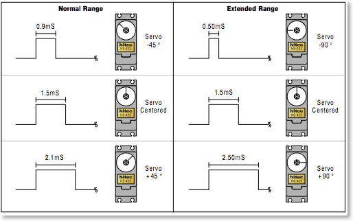
The problem was as follows: R/C servos are not all identical, and they're never really calibrated before they leave the factory. From the manufacturer’s perspective, there’s no reason to calibrate them. R/C models are nowhere near precise enough to justify the incredible costs to calibrate, and then re-calibrate over time, the servos. Thus, we really know nothing of the servos' behavior, aside from the fact that an ideal servo is in the neutral position at 1.5ms, +45deg at 2.1ms and -45deg at 0.9ms.
Furthermore, due to inconsistencies in the model, it's not
really clear where the end of the push-rod will end up
after a certain command.
The best way to eliminate all these unknowns is to simply
calibrate the servos once they're in the model. To do this
accurately, we need the help of a dial indicator.
The dial indicator is a very precise instrument, but
there's a problem. I needed to take 4500 samples (1 sample
per step * 500 steps * 3 tests * 3 servos = 4500 data
points), and I had no intention of doing this by hand.
Well, lucky me, I was in an image analysis lab. Why not get
the computer to do all the hard work? I could set up my
handy-dandy webcam in front of the dial indicator and
analyze the image.
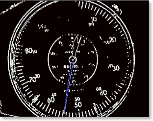
This actually worked quite well, with a success rate of over 80%, after a lot of tweaking of course. That still left me with around 900 data points to do by hand, but it wasn't so bad in the end. I’ve since then tweaked the algorithm and now regularly reach a success rate of 90%.
For a more detailed explanation of my automatic dial reader, click here.