Base
Plans and blueprints:
Truth to tell, I never had any blueprints, and you could almost claim I never had a plan. I jury-rigged everything on the spot, making design decisions based on how I felt. Is this the best way to go? For this sort of project, yes. There were so many unknown elements, and I was so out of my element, that it was impossible to decide ahead of time. The best-laid plans of mice and men could never have foreseen how the final project would look.
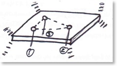
Moreover, this three-rod system effectively eliminate the problem of play, as the table driving mechanisms, in this case three Hitec HS-5745MG Digital servos, are always under compression, and thus always pushing on the table. What this means is that the servos are always pushing-- so there is never a moment when going from pushing to pulling, which is when play and backlash are the worst.
Finally, a three servo system has a very seductive advantage over traditional two-servo, two-axes systems. The axis of rotation of the table can be moved to anywhere in the universe! (For a given definition of "anywhere"). This lets us completely sidestep the "pea and spoon" effect by always having the table's axis of rotation located directly under the ball.
This so-called “pea and spoon” effect is what happens when you place an object at the end of a beam that then rotates so quickly the pea physically launches off the beam. This you have certainly observed during your childhood when you had fun loading peas into a spoon, placing the spoon on the edge of the table, smacking its handle, and sending the peas flying off to the other side of the room. For a more scientific explanation of the pea and spoon effect, click here.
Construction log:
My second attempt was with a servo motor that Eric had lying around his house.
This newfound knowledge in hand, we than started hacking on the computer’s parallel port. The parallel port is completely controllable-- up to the limitations of material and, as we were to discover, the operating system and driver. A bit of sample code (servo.zip) that we adapted in delphi and we had a working servo! Except...
The servo would spasm every few seconds. At first, we were at a loss for why it would act that way, but once I hooked up an oscilloscope, it was clear that the pulses themselves were at fault. We tracked this problem down to the operating system itself. Apparently Windows likes to seize control of the system completely, interrupting any other process, such as our servo pulse program. While this isn't particularly troublesome for most applications, this caused us a lot of problems as it would inevitably prolong the servo pulse, which the servo understood as a request for full deflection.
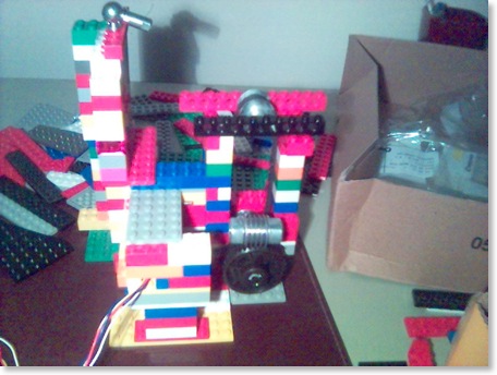
In a short time (2 hours or so), I had whipped up a second prototype.
This one worked quite well, aside from the fact that the periodic spasms would keep the ball from ever stabilizing. Still, it was a step in the right direction, and although the ball never stopped, it never quite fell off either.
A third prototype was subsequently made when my brother arrived from America, and with him the last vestiges of my lego collection, and the servos and servo controller finally came in the mail. Two thousand legos richer and three heavy-duty servos in hand, I made the first attempt at the two-dimension ball and plate machine. This prototype didn't take much longer than the others, and was quite successful, in spite of its bent paper-clip and transparent Plexiglas motorization.
Sadly, I have no photos, but it was certainly one of the more interesting machines I've ever built. In the metal shop at the Lycee Eiffel, all the machinists got a kick out of it's simplicity and the fact that it, well, it worked.
All in all, it was quite successful as a prototype. We were very impressed by the speed, accuracy, and torque of the servos, and the capabilities of the SSC-32 servo controller, sold by lynxmotion.com. (Let me take this time to put in a plug for Jim Frye at lynxmotion. Definitely some of the best customer service around.)
Still, a paper-clip base hardly is conducive to rigidity and precision, so the design was doomed from the start.
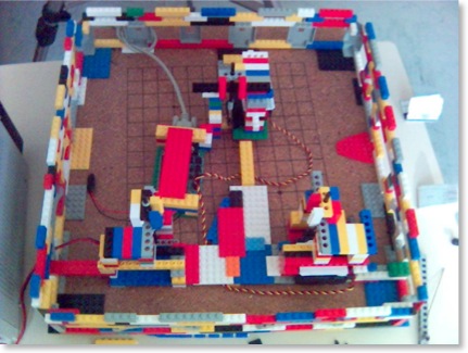
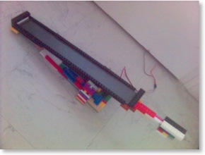
The next prototype was created when I realized that the best way to push is not paper-clips, but push-rods. I cannibalized the existing table and made a new series of modules for the servos. These modules took a fair amount of buttressing, as the weight of the table surface would tend to load the push-rods from the side, knocking the legos out of whack.
(In fact, I have had, and continue to have, and will always have— until I just glue the danged buggers together— problems with the legos separating. The mechanical joint is solid and tight, but doesn't resist rocking motion very well, as everyone who has ever played with legos can attest to. That's how you get them apart when they're stuck together, remember?)

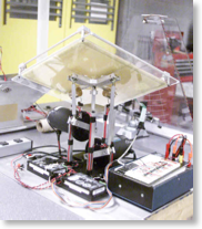
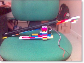
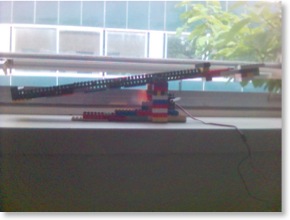
My last modification was to add springs that I made myself, found here on the web, a simple process that took only myself and an allen wrench as a combination winding shaft and winder. The springs are mounted underneath each servo arm and basically take some of the load off the servos. Servos tend to be less accurate when heavily loaded, and the weight of a 50cm x 50cm table surface + a pool ball really ate into their performance. By offloading this weight onto the springs, I not only increased the accuracy of the servos, but probably also greatly increased their life, as now the only work they have to do is fight against inertia. Kind of the opposite of a French bureaucrat’s job.
One important point in the spring design is that I used torsion springs pushing on the servo arm and not compression ones pushing directly on the underside of the table. This is because torsion springs, if wound a sufficient number of turns, vary little in their force as you load them. This is in contrast to compression springs which vary (more or less) linearly with distance, thus meaning that as the push-rod retracts the spring takes lots of weight, whereas when the push-rod extends the spring is completely off-loaded. Plus, reliable and consistent compression springs would have been really hard to make properly by hand.
The newer version of the table currently in Dijon uses a student-designed ingenious system of pulleys and counterweights to relieve the servos. The counterweight is attached to one end of a string and the other end is passed over a pulley and attached to the pushrod. The weight of the counterweight can be precisely matched to that of the table.